-
Advantages
Wide range of measurement
Due to its very small outer diameter, this resistance thermometer sensor can be inserted easily into any small measuring object. It is used over a wide range of temperatures, from -200℃ to +500℃.
Ouick response
This resistance thermometer sensor has a small heat capacity due to its small size and is highly sensitive to small changes in temperature and has a quick response.
Simple installation
Its flexible feature (bending radius more than double the sheath outer diameter) makes for simple and on-the-spot installation into complex configurations. The whole unit, except for the 70mm at the tip, can be bent to fit.
Long life span
Contrary to conventional resistance thermometer sensors which have a deterioration of resistance value with age or open circuits, etc., resistance thermometer sensor lead wires and resistance elements are insulated with chemically stable magnesium oxide, thus assuring a very long service life.
Excellent mechanical strength, and vibration resistance.
High performance is assured even under unfavorable conditions such as when used in vibrating installations, or in corrosive atmospheres.
Custom sheath outer diameters available
Sheath outer diameters are available, between 0.8 and 12 mm.
Custom long lengths available
Lengths are available up to 30 m maximum, depending on the outer diameter of the sheath.
-
Specification
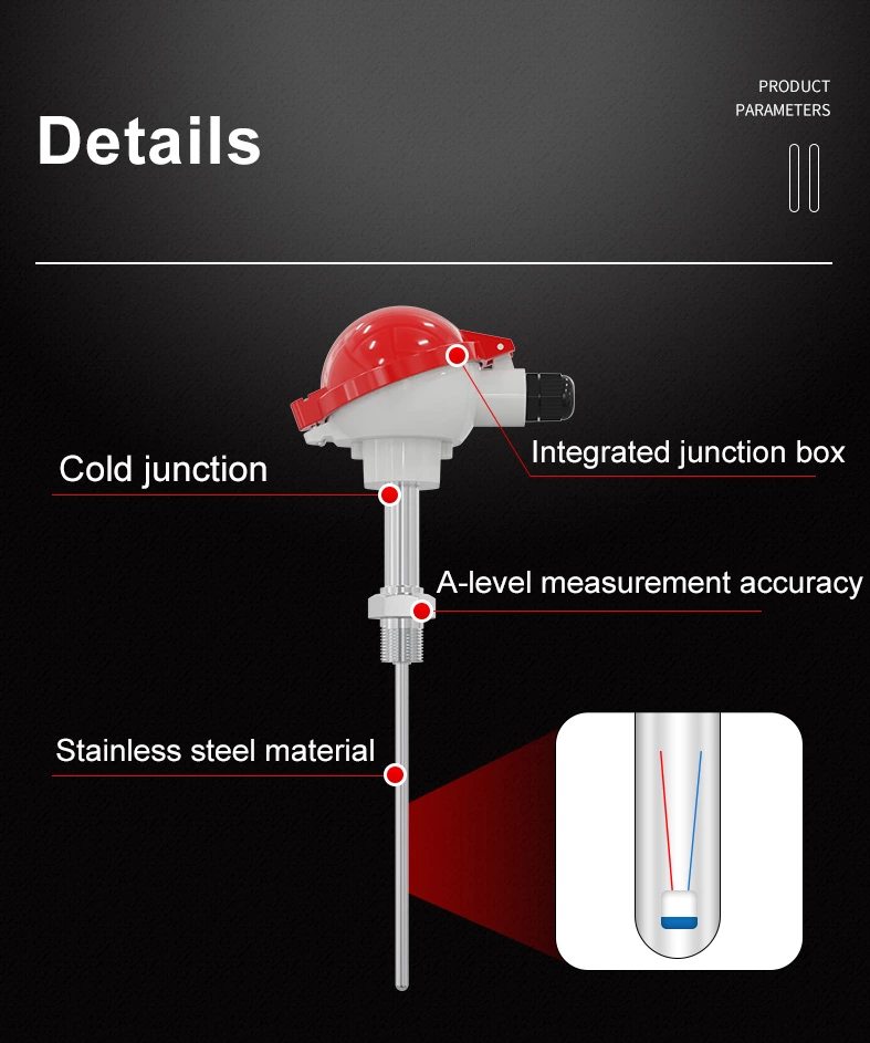

Type of Resistance thermometer sensor
| Nominal resistance value at℃ | Class | Measuring current | R(100℃) / R(0℃) |
| Pt100 | A | Below 2mA | 1.3851 |
| B | |||
| Note | |||
| 1. R(100℃) is the resistance value of the sensing resistor at 100℃. | |||
| 2. R(0℃) is the resistance value of the sensing resistor at 0℃. | |||
Standard Specifications of Resistance Thermometer Sensor
| Sheath | Conductor wire | Sheath | Approx | ||||
| max length | weight | ||||||
| OD(mm) | WT(mm) | Material | Dia(mm) | Resistance per wire | Material | (m) | (g/m) |
| (Ω/m) | |||||||
| Φ2.0 | 0.25 | SUS316 | Φ0.25 | - | Nickel | 100 | 12 |
| Φ3.0 | 0.47 | Φ0.51 | 0.5 | 83 | 41 | ||
| Φ5.0 | 0.72 | Φ0.76 | 0.28 | 35 | 108 | ||
| Φ6.0 | 0.93 | Φ1.00 | 0.16 | 20 | 165 | ||
| Φ8.0 | 1.16 | Φ1.30 | 0.13 | 11.5 | 280 | ||
| Φ9.0 | 1.25 | Φ1.46 | 0.07 | 21 | 370 | ||
| Φ12 | 1.8 | Φ1.50 | 0.07 | 10.5 | 630 | ||
| Φ3.0 | 0.38 | Φ0.30 | - | 83 | 41 | ||
| Φ5.0 | 0.72 | Φ0.50 | ≤0.65 | 35 | 108 | ||
| Φ6.0 | 0.93 | Φ0.72 | ≤0.35 | 20 | 165 | ||
| Φ8.0 | 1.16 | Φ0.90 | ≤0.25 | 11.5 | 280 | ||
| Φ9.0 | 1.25 | Φ1.00 | ≤0.14 | 21 | 370 | ||
| Φ12 | 1.8 | Φ1.50 | ≤0.07 | 10.5 | 630 | ||
Tolerance of RTDs to Temperature and Applicable Standard Table
| IEC 751 | JIS C 1604 | |||
| Class | Tolerance (℃) | Class | Tolerance (℃) | |
| Pt100 | A | ±(0.15 +0.002|t|) | A | ±(0.15 +0.002|t|) |
| ( R(100℃)/R(0℃)=1.3851 | B | ±(0.3+0.005|t|) | B | ±(0.3+0.005|t|) |
| Note. | ||||
| 1.Tolerance is defined as the maximum allowable deviation from the temperature VS. resistance reference table. | ||||
| 2. l t l=modulus of temperature in degrees Celsius without regard to sign. | ||||
| 3. Accuracy class 1/n(DIN) refers to 1/n tolerance of class B in IEC 751 | ||||
